
RFS Technologies Air Dielectric Cable [HCA] High Power RF Air Cable
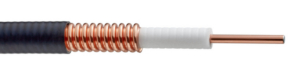
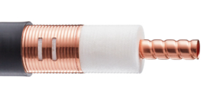
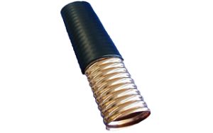
RFS Technologies' air dielectric cables are air filled coaxial cables which consist of an inner conductor and an outer conductor
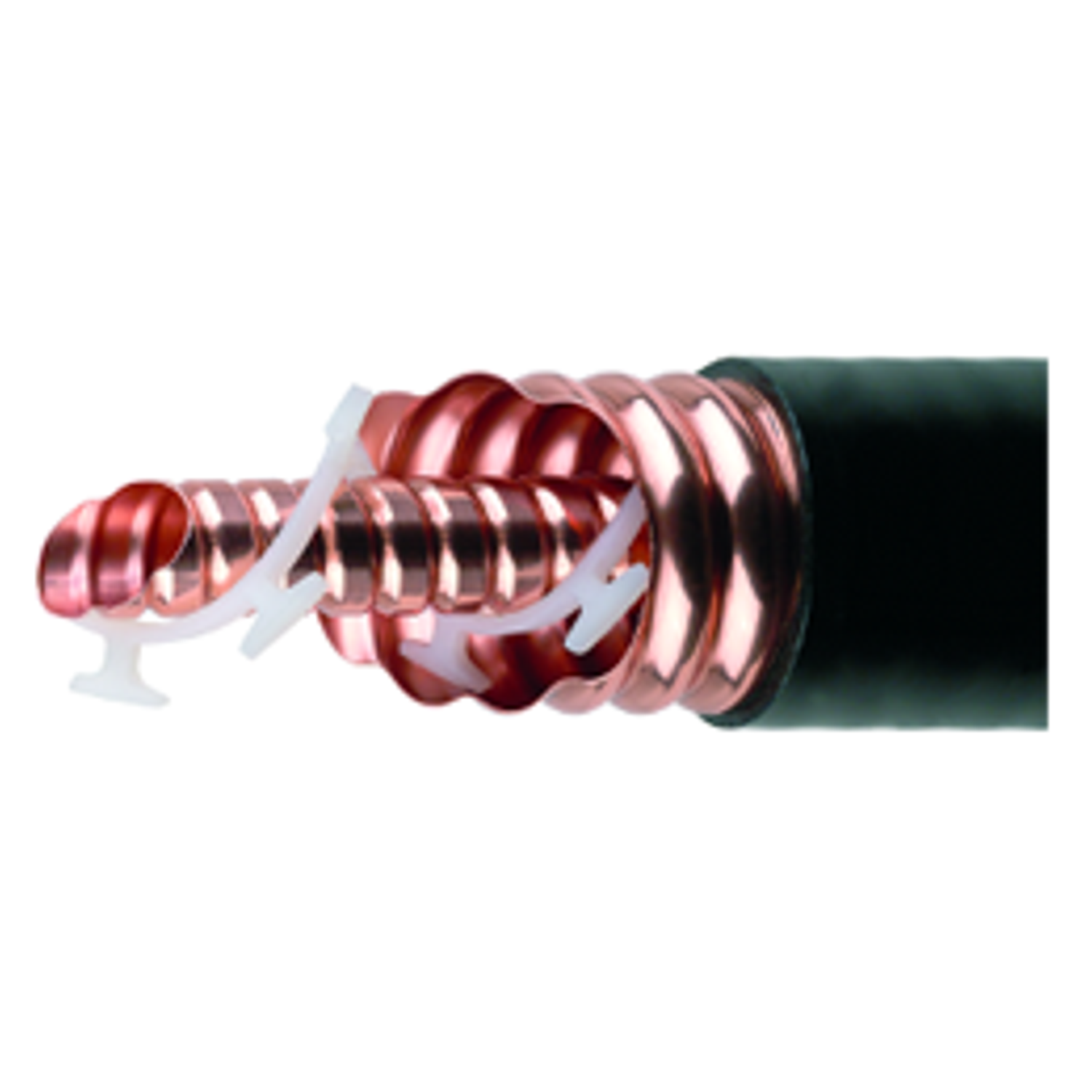
HCA air dielectric cables are high-power coaxial transmission lines designed for efficient RF signal transmission in broadcast, cellular, and microwave systems. They use air as the primary dielectric with a helical spacer, enabling extremely low signal loss and high power handling for long-distance RF feedlines.
Key Benefits
- Very low attenuation for efficient long-distance RF transmission
- High power handling capability for broadcast and high-power transmitters
- Excellent shielding with corrugated copper outer conductor
- Low VSWR and low intermodulation distortion for stable RF performance
- Better heat dissipation due to air dielectric design
Top Sellers
| HCA78-50JM | 7/8″ Air Dielectric Cable |
| HCA158-50JM | 1-5/8″ Air-Dielectric Coaxial Cable, 50 ohm, Low Loss and High Power Rating |
| HCA300-50JM | 3″ Low Loss Air Dielectric Cable |
| HCA400-50JM | 4″ Low Loss Air Dielectric Cable |
Typical Specifications
| Parameter | Typical Value |
| Characteristic Impedance | 50 Ω |
| Maximum Frequency | ~3 GHz |
| Velocity Factor | ~93% |
| Dielectric Type | Air with helical polyethylene spacer |
| Outer Conductor | Corrugated copper |
| Attenuation | Very low compared with foam coax |
| Peak Power Rating | Up to ~70 kW (depending on size) |
| VSWR | ~1.2 typical |
Example: a 7/8″ HCA cable can handle ~73 kW peak power with very low insertion loss.
Available Cable Sizes
Typical HCA cable sizes include:
| Size | Typical Application |
| 7/8″ | Small broadcast or cellular feedlines |
| 1-1/8″ | Medium RF systems |
| 1-5/8″ | High-power base stations |
| 2-1/4″ | Broadcast transmitters |
| 3″ – 6-1/8″ | High-power broadcast or radar systems |
Larger cables provide lower attenuation and higher power capacity.
Frequency Range
Typical supported frequency range:
| Frequency | Typical Applications |
| VHF | Radio broadcasting |
| UHF | TV broadcasting |
| 700 MHz – 2.7 GHz | Cellular networks |
| Up to ~3 GHz | Microwave communication |
These cables are widely used in broadcast and high-power RF transmission systems.
Transmission Line Type
- Air-dielectric coaxial transmission line
- Inner conductor supported by helical dielectric spacers
- Corrugated copper outer conductor
- Characteristic impedance 50 Ω
Air dielectric cables offer lower loss and higher power capability compared to foam dielectric cables.
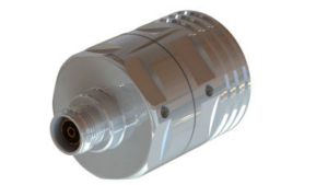
Common Connector Types
Typical connector interfaces include:
| Connector Type | Typical Use |
| EIA flange connectors (1-5/8″, 3-1/8″, 4-1/2″, 6-1/8″) | High-power broadcast systems |
| 7/16 DIN connectors | Cellular infrastructure |
| N-type connectors | Smaller RF equipment |
| Gas-stop / gas-pass connectors | Pressurized cable systems |
These connectors maintain high power handling and impedance matching.
Typical Applications
HCA air dielectric cables are commonly used in:
- TV and radio broadcast transmitters
- High-power cellular base stations
- Microwave communication links
- Radar systems
- Antenna feedlines for large RF systems
Simple Explanation
- Air dielectric cable (HCA) → designed for very high power RF transmission
- CELLFLEX feeder cable → low-loss cable for cellular infrastructure
- RADIAFLEX cable → radiating cable acting as a distributed antenna
Plenum Coax Cables
RFS Technologies ClearFill®Line
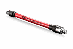
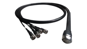
RF Factory-Fit Jumper
RFS Technologies CELLFLEX® Factory‑Fit & ClearFill®Line
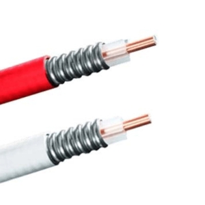
CELLFLEX RF Feeder Cable
RFS Technologies CELLFLEX RF Feeder Cable
RADIAFLEX® RF Feeder Cable
RFS Technologies RADIAFLEX® RF Feeder Cable
RADIAFLEX Connectors & Accessories
RFS Technologies CELLFLEX RF Feeder Cable
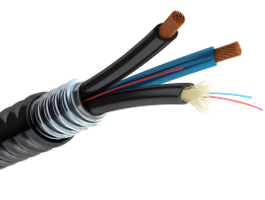
Air Dielectric Cable [HCA] High Power RF Air Cable
RFS Technologies' air dielectric cables are air filled coaxial cables which consist of an inner conductor and an outer conductor
![Air Dielectric Cable [HCA] High Power RF Air Cable](https://www.alliancecorporation.ca/wp-content/uploads/2026/03/hca158-50jplb-300x300.png)
FLEXWELL® Premium Elliptical Waveguide
RFS Technologies FLEXWELL® elliptical waveguide is constructed of longitudinally continuous seam welded, highly conductive copper tube, corrugated and precision formed into an elliptical cross section.
HYBRIFLEX Optical Fiber & Power Cables – Hybrid
RFS Technologies - Custom Hybrid Cables Available
Dragon Skin System
RFS Technologies coaxial cable certified under UL 2196